Projects
Welcome to my projects page! This page includes all of the projects that I have been a part of over the last couple of years. These projects range from extracurricular activities to academic projects.
ASME electric Human Powered Vehicle Challenge (eHPVC)

e-HVPC Report
Overview Of Competition:
ASME's e-Human Powered Vehicle Challenge (e-HPVC) is an engineering design and innovation competition that gives students the opportunity to network and apply engineering principles through the design, fabrication, and racing of human powered vehicles. The competition is divided into three sections: drag race, endurance race, and design competition. The three parts of the competition forced us to consider every aspect of the vehicle. In order to meet safety standards of the competition, the vehicle needed to have 8-meter turn radius, be able to withstand 2670 Newtons vertically, 1330 Newtons horizontally, have a maximum allowable elastic deformation of 3.8 cm, come to a stop from a top speed of 25 km in 6 m, and brakes capable of stopping the electric propulsion. With these design parameters, we worked from scratch to build a competition ready vehicle in less than 6 months.
Design Aspect:
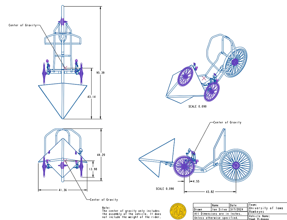
Early on, the project involved a lot of research into commercially available bikes and trikes, materials, previous participants, and different drive trains. The first couple of months were spent discussing the benefits of each design. As a team, it was decided that the design we would implement was a trike with a hub motor on the rear wheel and a simplistic, yet effective roll cage. After finalizing a parts list, it was decided that buying an existing trike frame and modifying it would be more effective monetarily and timewise. The trike frame would be manufactured out of aluminum because its low-weight and relatively strong material properties. Choosing aluminum proved to be challenge because the University of Iowa had no facilities capable of welding aluminum. Therefore, we partnered with Kirkwood Community College to weld the roll cage to the frame. The roll cage pipes were bent in-house before sending it and the frame to Kirkwood. To have them accurately weld the pieces together manufacturing drawings were created from the CAD files that I made in Creo. The roll was modeled with a design constraint of bend diameters of 5 inches because it was the only die available at the University of Iowa. Additionally, the roll cage had to ensure that the rider's head and arms would not touch the ground if the vehicle flipped. Structural analysis with static loads was done in Abaqus to ensure that the frame and the roll cage met the safety standards. To improve the aerodynamics of the vehicle, a fairing was added to the front of the vehicle. Several designs were considered including a design model of Herky. The final design was decided by performing a CFD of the different fairings and the frame and analyzing feasibility of manufacturing. A simple of pyramid made out of polycarbonate was determined to best for the competition. The electrical propulsion of the vehicle was purchased as a package and implemented. The vehicle had to meet a secondary electrical system of lights, horn, emergency switch, and speedometer.
Outcome:
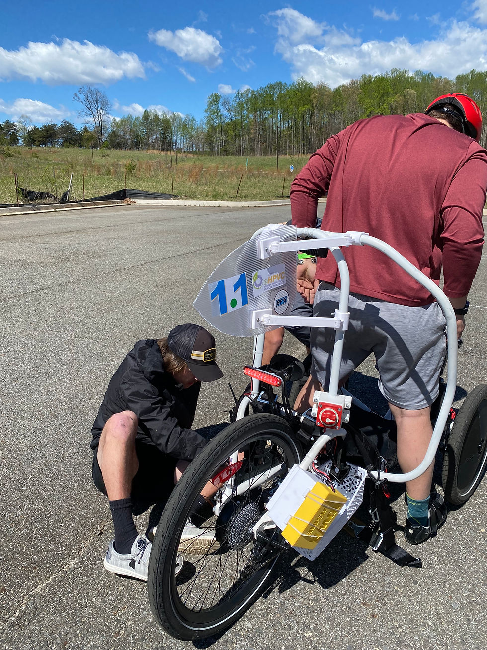
The competition happened on April 12th and 13th, and our team placed 4th in the drag race, 7th in the endurance race, 6th in the design portion. Overall, our team placed 6th in the competition. During the drag event, failure of our brackets holding of our fairing occurred due to cross winds. The brackets were 3D and meant to withstand tensile loading but not shear. The fairing created a large moment that induced a shearing failure in the bracket. This wasn't a critical failure for the vehicle and allowed us to continue performing. However, in the endurance race, I applied the brakes to quickly which caused the vehicle to flip and bend the front left tire. This damaged the speed controller and destroyed our motor assistance. We quickly fixed the bent wheel and continued the competition without any electronics. The roll cage successfully protected me from any injuries which showed that our analysis was correct. Overall, I learned a lot about creating a product from start to finish. The project taught me about welding, manufacturing, structural analysis, aerodynamics, and collaboration with outside organizations.
Industrial Internet of Things Snack Launcher


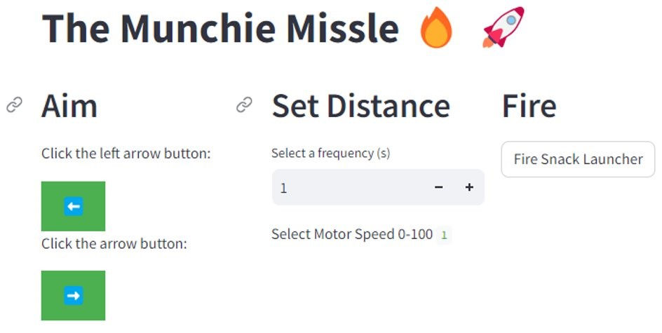
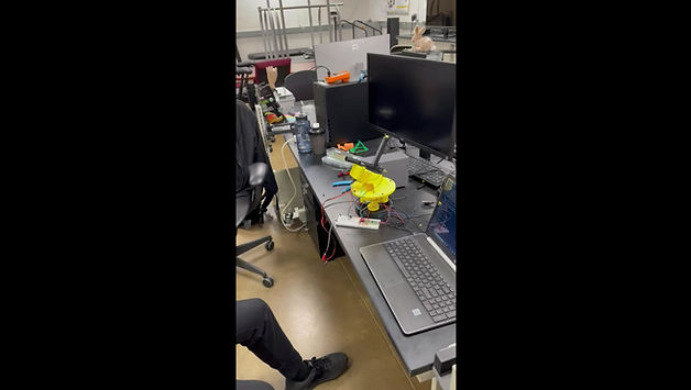
The IoT Snack Launcher project aspired to create a fun and efficient device using automation and remote control for quick access to a variety of snacks. The specific project goals included developing a functional prototype, creating a user-friendly mobile app or web interface, ensuring compatibility with Wi-Fi, and designing the device for easy maintenance. The project's scope can be adjusted based on available resources, either starting with a simplified prototype and adding advanced features later or expanding to include integration with voice assistants and other IoT devices. The criteria for the snack launcher were meticulously crafted, encompassing features like automatic loading, full 360-degree rotation, snack launching, adjustable distance, and vertical airtime. The design process involved addressing constraints such as power consumption, safety regulations, and budgetary limitations to ensure a safe, functional, and cost-effective device. The graphical user interface (GUI) serves as the control hub, allowing users to control the launcher's direction, motor speed, and firing times. Notably, the GUI provides dynamic control over the motor speed, influencing the firing distance of the snacks. The design parameters and goals were set before modeling, considering automatic loading, full rotation, adjustable distance, and vertical airtime. The creation of the snack launcher involved innovative solutions, including a solenoid for automatic loading, a planetary gear system for full rotation, and dual DC motors with rubber wheels for enhanced launch distance. The snack launcher project embodies critical design parameters, navigating challenges related to safety, user experience, market viability, and cost-effectiveness. The iterative development process considered power constraints, safety regulations, and budget limitations, resulting in a functional and user-friendly device. The total cost of the project was $96.46, considering various components and materials. Continuous user feedback and iterative improvements are essential elements in refining the snack launcher to meet evolving user preferences and needs.
ASME's Hovercraft Team
During the 2022-2023 academic year, I lead a competition team for ASME's IAM3D EFx event. We started designing the hovercraft from scratch in October. Before modeling the hovercraft in Creo Parametric, the design process was an accumulation of research, brainstorming, and discussion. Throughout testing and simulations, we continually changed the design as needed. We coordinated with another student organization, Iowa 3D Print Club, to print some of the largest pieces. All of the non-electronic parts on the Hovercraft were either 3D printed. Together, everything was assembled before the competition in Milwaukee in late April. We got to tour Milwaukee tools and Komatsu during the conference. Overall, the competition and process was learning experience and loads of fun.


ASME Drone Competition

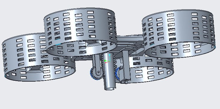
During the 2021-2022 academic year, I lead a design team for an in-house competition. This was originally the ASME's IAM3D EFx competition in 2020 but was cancelled due to COVID. That year's team had a different drone design. The competition featured a course that the drone had to navigate while picking up and securing a 3D printed block with a washer on top every lap. In 2021, the ASME conference was still going to be held virtually, so we decided that we were going to do an in-house competition. The drone has a simple rack and pinion mechanism to lower a magnet to pick up the block. Unfortunately, the drone was never fully assembled, due to some supply issues. Only the body of the drone was printed. The drone design was further modified and optimized for a final project. The design was changed to feature smaller motor cages and multi-axis pick-up mechanism. The entire design was made using Creo Parametric. The presentation attached below is a copy of the final product. This served as a good experience on additive manufacturing, tolerances, and design realization.
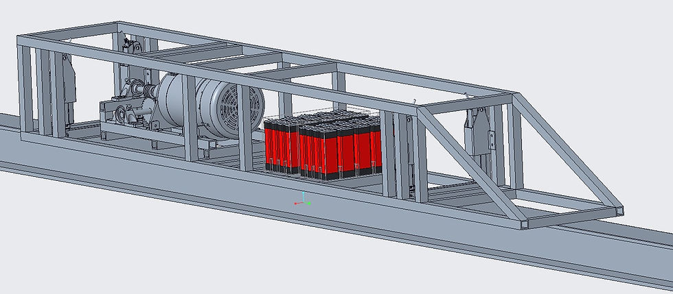
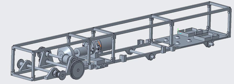
Hyperloop at Iowa
Hyperloop at Iowa was formed a couple of years before I came to the University of Iowa. I have been a part of Hyperloop since my freshman year. Then, the club was still in beginning stages. The organization had no funding or no concrete design. Over the years, the plan was to create a pod to compete in the SpaceX competition held in California. However, since the organization was new and small, there wasn't enough funding to create a full-scale model of the pod. Thus, when I took over as president, we already had a fundamental design in place but no funding to buy the materials needed to create the pod. So, we decided to model and 3D print a prototype using a 1/12 scale of our real design. This would serve as testing prototype as well as a learning experience. Over the last two years, as president we've successfully built an initial prototype, and modified it so that it can be manufactured and built more easily. The modifications include adding a gear system to convert the high torque from the motor to a high rpm. As the organization gains more funding and members, the hope is to transition from the prototype to a full-scale model.

American Institute of Aeronautics and Astronautics
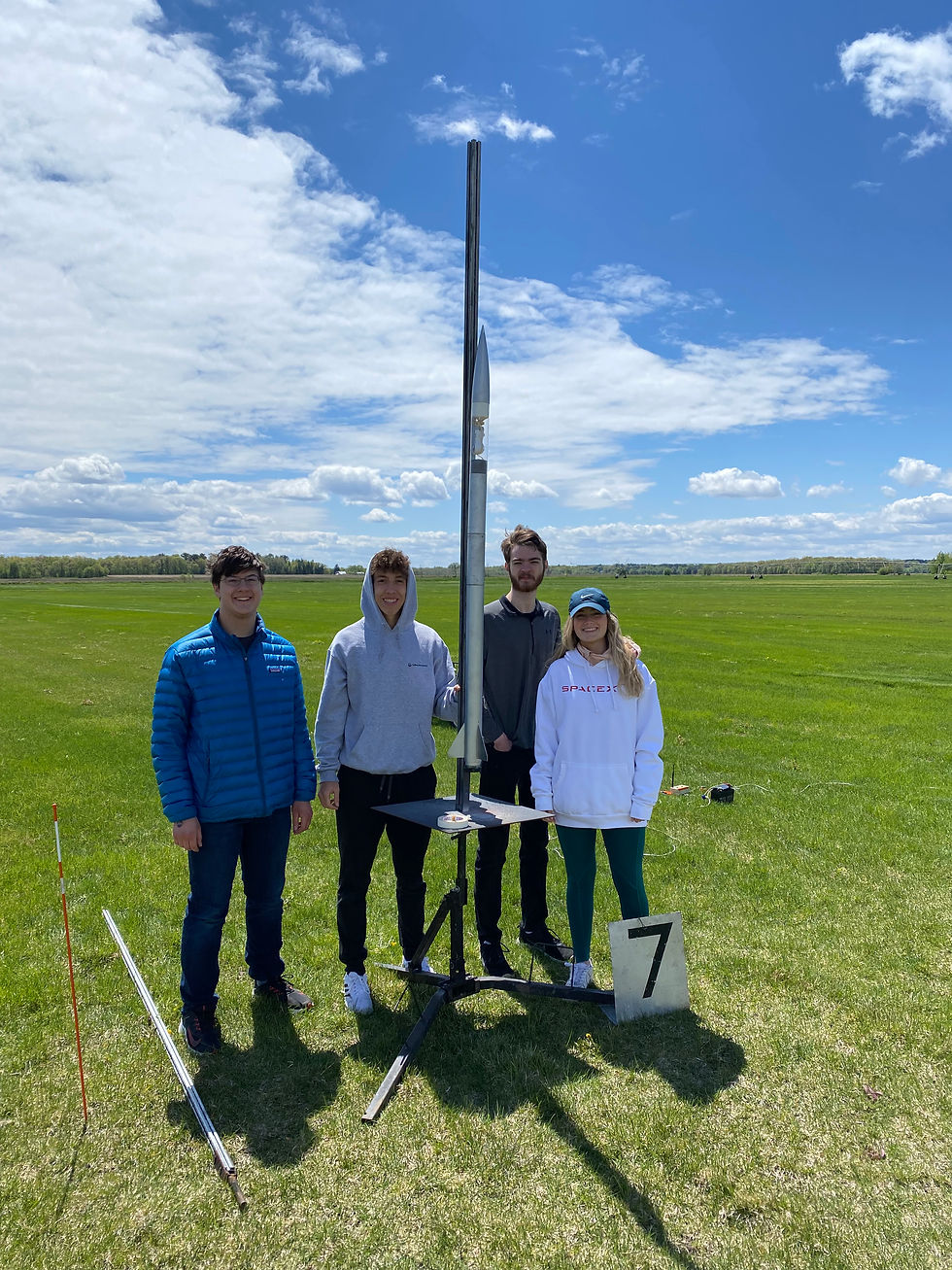


Over the last four years, I have been a part of the American Institute of Aeronautics and Astronautics club at the University of Iowa. Annually the organization participates in the Midwest High Power Rocketry competition in Minnesota. Each year, there is a different task to complete in the competition. My first in the organization, the objective was to land a rocket upright without the use of propellants. Due to the pandemic, the competition was cancelled for the following next two years. Upon return to the competition, the objective was to create a fleet of rockets with a theme. Our organization decided to try building an assortment of uniquely built rockets with a color and naming theme after Iron Man suits. My group was responsible for designing and building a rocket that would hit Mach speeds and would house a 360 camera in acrylic tubing. The fins were cut out of carbon fiber using the engineering machine shop. Sneaky was designed using OpenRocket, a commonly used model rocketry software. With OpenRocket the fins, length, and placement of the avionics were optimized using the optimization tool. Sneaky was set to go around 1.3 Mach on the designed motor but was downgraded due to some safety concerns. In the 2023 competition, the objective was to direct the rocket towards a landing pad and land upright. The entire rocket was designed but was unfortunately scrapped due to supply issue. Instead, I built a certification rocket.
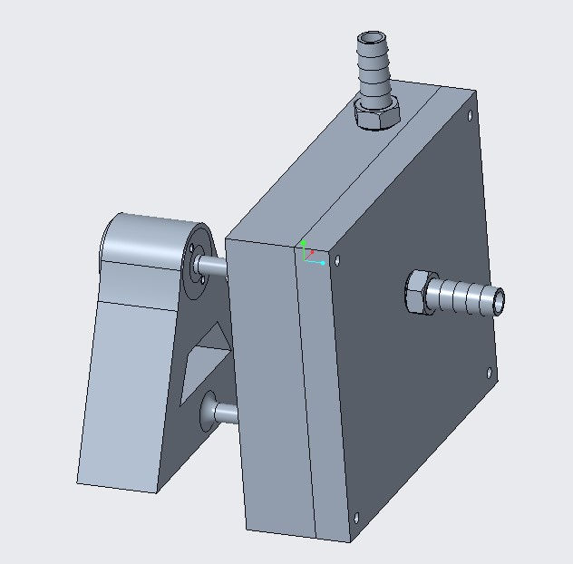
Manufactured Centrifugal Pump
In one of my engineering courses, manufacturing process, we learned about manufacturing techniques and practices. Each lab was a demonstration and practice on machines such as the lathe, CNC machine, etc. The final project was to design and manufacture a small centrifugal pump over 6 weeks using the techniques taught in the lab. Each group was given a small 9-volt DC motor, required to 3D print one piece of the pump, and required to CNC another section. Our group used the CNC to manufacture the volute casing for the pump. The casing was manufacture out of PVC plastic. The motor stand, impeller, and channel guide were 3D printed using designs created in Creo parametric. An aluminum rod was used to rotate the impeller inside the watertight casing. The presentation given after the class competition is linked below.


Transient Thermal Management of Avionics - Collins Aerospace
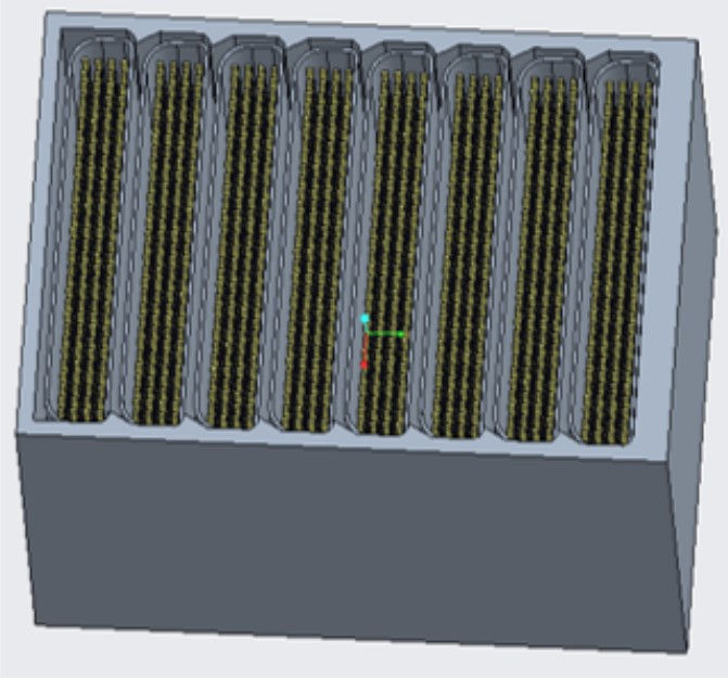


The objective of my mechanical senior design was to research and generate a solution for passively cool avionics for a single time use and multiple use. This was a semester long project sponsored by Collins Aerospace. The first half of the project was researching different possible solutions. This included using an endothermic reaction to trigger when the avionics reached a critical temperature. This was disregarded because the endothermic reactions that didn't create harmful byproducts required an activation energy much higher than the critical temperature. Instead, the solution provided by the group was to use a phase change material, paraffin wax, to absorb and keep the heat generated by the avionics system until the module is no longer in use or can be replaced. The design was chosen to be modular so that the system can be quickly replaced after the flight or so that maintenance is easy. After the models of the modules were created using Creo Parametric and Solidworks, 2D and 3D simulations were performed in Ansys using its solidification and melting capabilities. The objective of the simulations was to determine the length of time until paraffin wax was completely melted. After each simulation, the spacing and number of fins were changed to optimize the heat absorbed.
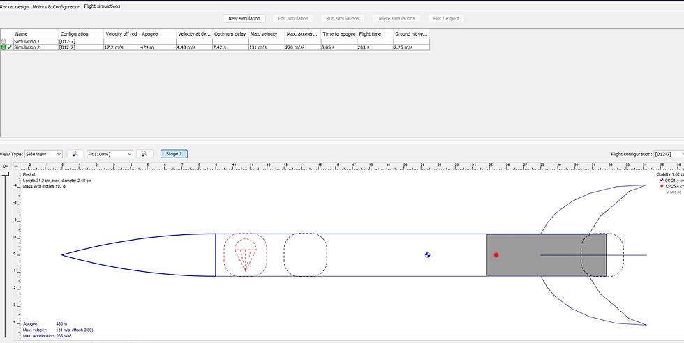
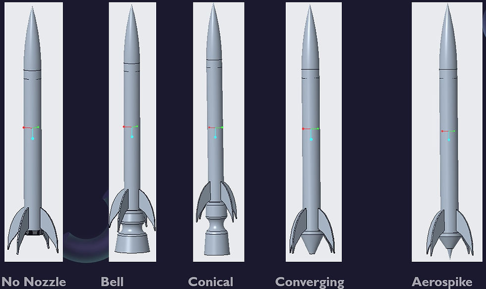
History of Rocket Nozzles
In one of my engineering courses, propulsion engineering, we covered the main governing equations for propulsion for ramjets, scramjets, rockets, turboprops, etc. We also covered the history of many projects conducted by NASA and other aerospace companies so that we could understand the successes and failures of others. Our final project was to either dive deeper into such projects or build a propulsion related project. My project looked at the history of rocket nozzles and experimenting with 3D printed nozzles. I looked at the advantages and disadvantages of different types of nozzles. After reading research papers on the different types of nozzles, I 3D printed bell, conical, plug, and converging nozzles. Each nozzle was printed out of PLA and attached to assembled small rockets with D class motors. Unfortunately, I encountered several issues, primarily that the PLA wasn't able to withstand the heat generated from the motor for the duration of the flight. The presentation covering everything I learned is linked below.